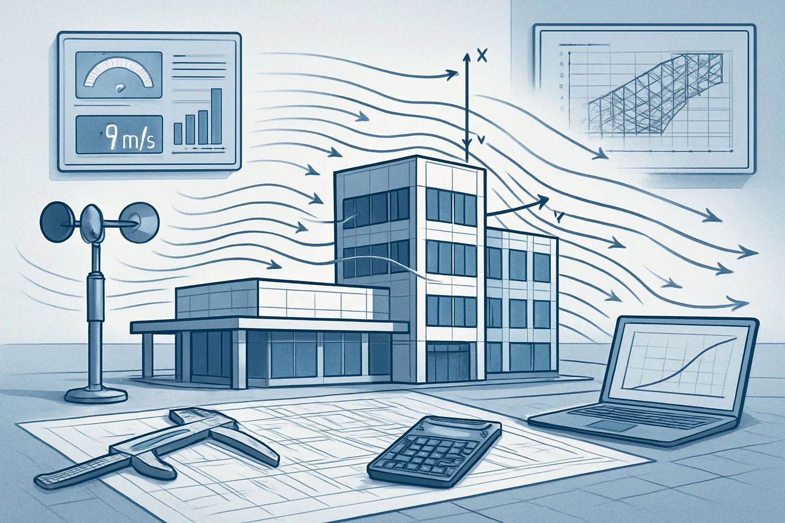
Wind Load Calculation, Analysis for Safe Structural Design of Commercial Projects
Wind loads are a critical factor in building design. They push against structures, causing potential damage if not accounted for properly. Every building must be designed to withstand these forces safely.

Wind load calculation determines the amount of pressure a structure will face during high wind events. This pressure varies based on building height, shape, location, and surrounding terrain. Engineers use specific formulas and codes to ensure buildings can resist these forces without failure.
The consequences of inadequate wind load design can be severe. From roof damage to complete structural collapse, proper calculations protect both property and lives. These calculations form the foundation of resilient construction in areas prone to high winds or severe weather events.
What Wind Load Means For Commercial Buildings
Wind loads significantly impact commercial buildings' structural integrity and safety. Buildings must withstand both direct wind force and the suction effects that can damage facades, roofs, and structural elements.
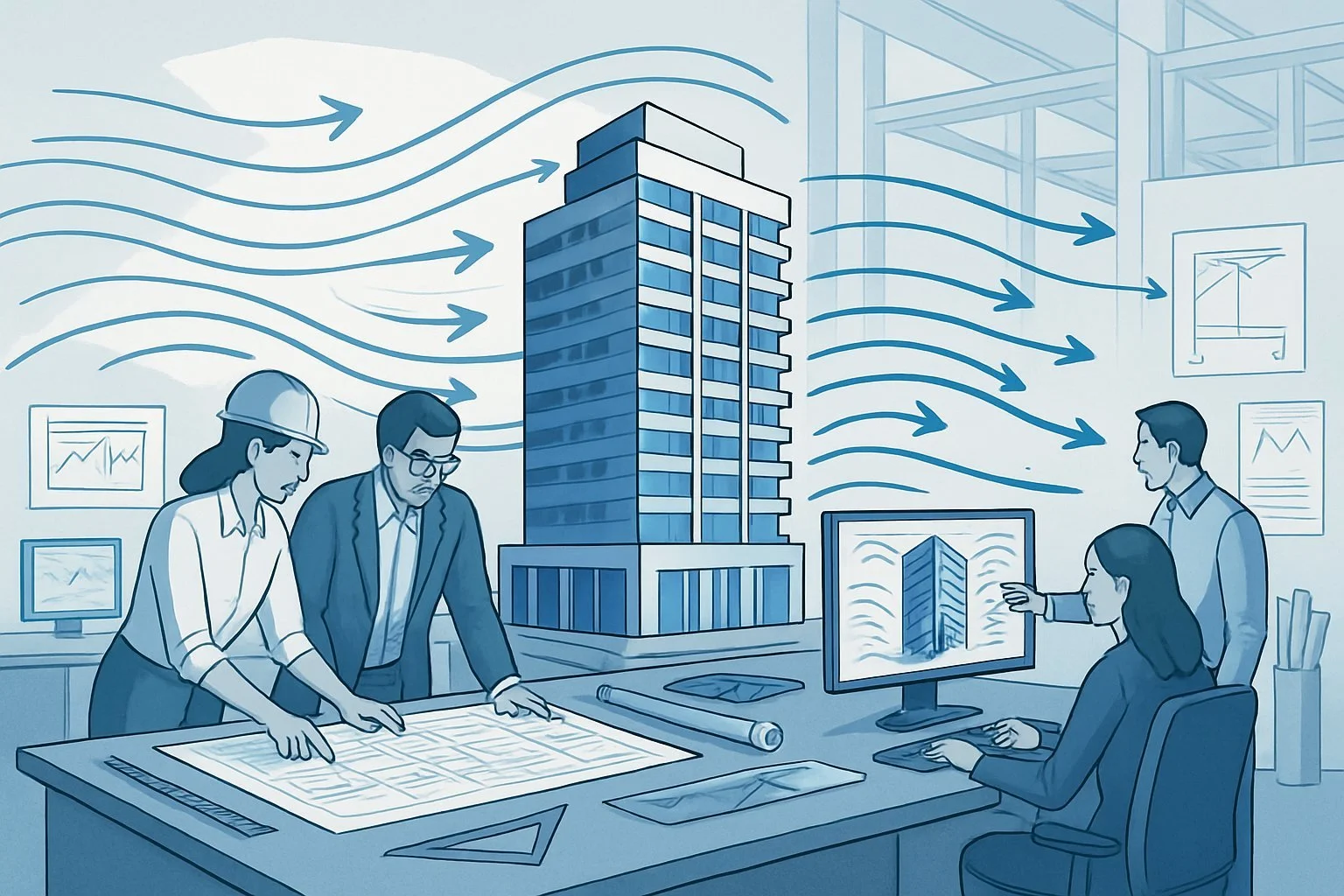
How Wind Interacts With Large Structures
Wind creates pressure against building surfaces, with forces varying based on building height and shape. Taller commercial structures face stronger winds at higher elevations, experiencing up to 50% more force than at ground level.
The dynamic pressure from wind creates positive pressure on windward faces while generating negative pressure (suction) on leeward sides. This pressure differential can reach 30-40 psf in high wind regions.
Buildings with unusual shapes may experience unpredictable wind patterns. Square buildings typically have drag coefficients of 1.3-1.5, while rounded structures may reduce this to 0.7-0.8.
Wind tunneling between buildings can amplify these forces by 20-30% in urban environments.
The Unique Risks For Office Buildings, Warehouses, And Mixed-Use Developments
Different commercial building types face distinct wind-related challenges:
Office Buildings:
Glass curtain walls are vulnerable to pressure fluctuations
Multiple entry points create pressure imbalances
Mechanical systems on rooftops are at risk during high winds
Warehouses:
Large, uninterrupted wall surfaces catching the wind like sails
Wide-span roofs are susceptible to uplift forces
Loading dock areas create pressure differentials
Mixed-Use Developments:
Varying height sections create turbulence zones
Multiple roof levels forming wind "catch points"
Diverse façade materials with different wind resistance properties
These vulnerabilities require specific engineering solutions based on building type, location, and height.
Why Commercial Roof Design Is Especially Vulnerable
Commercial roofs face heightened wind vulnerability due to their design and exposure. Flat roofs, common in commercial buildings, create perfect conditions for wind uplift, especially at edges and corners where wind can generate lifting forces 2-3 times greater than in central areas.
Parapet height significantly affects wind behavior. Too short (under 3 feet), and they barely disrupt airflow; too tall, and they create turbulence zones that increase uplift forces.
Roof-mounted equipment (HVAC units, satellite dishes) creates obstruction points where wind can exert concentrated force. Each piece effectively increases the drag coefficient in its vicinity.
Membrane roofing systems, popular for commercial buildings, can act like sails if not properly secured, with failure typically starting at the edges before progressing inward.
Visual: Side-By-Side Graphic Of Flat-Roof Vs. Sloped-Roof Wind Effects
Flat-Roof Wind Dynamics:
Wind moves horizontally across the surface
Creates uplift forces at edges and corners (30-50% stronger)
Forms vortices that can peel back roofing materials
Pressure: -25 to -40 psf at perimeter in 90 mph winds
Sloped-Roof Wind Dynamics:
Wind follows the contour of the roof surface
Windward slope: positive pressure (+10 to +20 psf)
Leeward slope: negative pressure (-15 to -25 psf)
Ridge experiences the highest pressure differential
Steeper slopes (>30°) reduce uplift forces by 15-20%
This comparison illustrates why commercial buildings with flat roofs require specialized attachment systems, ballasting, or mechanical fastening to counter these significant uplift forces.
Variables That Change The Equation
Wind load calculations depend on several key factors that can significantly alter your results. These variables must be carefully assessed to ensure your structure can withstand the forces nature will apply.
Site Location And Regional Wind Speeds
Wind speeds vary dramatically by geographic location. Coastal areas typically experience higher wind speeds than inland regions. The basic wind speed in Miami, Florida (170 mph) differs greatly from Chicago, Illinois (105 mph).
Wind maps in engineering codes divide the United States into different wind zones. These zones reflect historical data and statistical analysis of extreme wind events.
Regional Differences to Consider:
Hurricane-prone regions (Atlantic and Gulf Coasts): 130-180 mph
Tornado Alley (Midwest): 90-115 mph
Mountain regions: Variable due to terrain effects
Pacific Northwest: 85-110 mph
Engineers must obtain the basic wind speed from reliable sources like ASCE 7-16 wind maps or local building codes.
Height, Shape, And Orientation Of Your Structure
Taller structures face greater wind pressures. Wind speed increases with height above ground due to reduced friction from surface features.
A 100-foot-tall building experiences significantly higher wind pressure at its top than at ground level. This variation creates a wind profile that engineers must account for.
Building shape dramatically affects wind load. Structures with the following characteristics face different challenges:
Boxy buildings: Experience direct pressure on windward faces
Rounded structures: May reduce wind resistance
Complex shapes: Create unpredictable wind patterns
Orientation matters too. A rectangular building with its narrow end facing prevailing winds experiences less overall force than the same building oriented broadside.
Nearby Obstructions Or Open Terrain
Surrounding terrain significantly affects wind loads through exposure categories defined in ASCE 7-16:
| Exposure Category | Description | Effect on Wind Load |
|---|---|---|
| Exposure B | Urban/suburban areas | Reduced wind loads |
| Exposure C | Open terrain, grasslands | Moderate wind loads |
| Exposure D | Flat, unobstructed areas near water | Highest wind loads |
Buildings in Exposure B benefit from the shielding effect of surrounding structures. A high-rise downtown experiences different wind patterns than an identical building in an open field.
Nearby hills, valleys, and large buildings create complex airflow patterns that may increase or decrease wind pressure at specific points on a structure.
Local Building Code Wind Maps (ASCE 7-16, IBC, Etc.)
Building codes provide specific wind load requirements that vary by jurisdiction. ASCE 7-16 serves as the foundation for most modern U.S. building codes.
The International Building Code (IBC) adopts ASCE 7 standards with occasional modifications. Local amendments may impose stricter requirements based on regional concerns.
Wind maps in these codes provide:
Basic wind speeds for different return periods
Special wind regions requiring site-specific analysis
Hurricane-prone region boundaries
Wind directionality factors
Engineers must reference the most current adopted code for their jurisdiction. Using outdated wind maps can result in either unsafe designs or unnecessary construction costs.
Visual: Map Overlay Of U.S. Wind Zones For Commercial Development
The United States features distinct wind zones that directly impact commercial development requirements. The eastern seaboard and Gulf Coast face the highest design wind speeds due to hurricane risk.
Key Wind Zone Considerations:
Special Wind Regions (mountains, gorges) require site-specific studies
Hurricane-prone regions require impact-resistant glazing
The Risk Category of the structure affects the design wind speed
The central plains have moderate basic wind speeds but higher tornado risk. Western states generally have lower design wind speeds except in mountain passes and coastal areas.
Commercial developers should conduct preliminary wind assessments early in site selection. A property in a 170 mph wind zone requires significantly more structural investment than one in a 105 mph zone.
Where Wind Load Shows Up In The Design Process
Wind loads impact multiple components of building design, requiring careful analysis at various stages to ensure structural integrity and safety.
Foundation Anchoring And Lateral Resistance
Wind forces create uplift and lateral pressures that foundations must resist. Proper anchoring systems transfer these loads safely into the ground.
For commercial buildings, foundations typically include tie-downs, anchor bolts, and hold-downs specifically sized to resist calculated wind loads. The mean roof height directly influences these calculations, as taller structures experience greater wind pressures.
In high-wind regions, foundations may require deeper footings or more robust connection systems. Engineers analyze the overturning moment caused by wind to determine the necessary counterweight in the foundation design.
Design codes like ASCE 7 provide minimum requirements for foundation resistance to wind loads based on location and building type.
Curtain Walls And Cladding Connections
Exterior cladding systems face direct wind exposure and require careful connection design. These elements must withstand both positive pressure (windward face) and negative pressure (suction on leeward faces).
Connection points between cladding panels and the main structure must:
Accommodate building movement
Resist calculated wind pressures
Prevent water infiltration
Maintain thermal performance
Glass curtain walls require special attention as their deflection limits under wind load are critical for performance. Engineers calculate maximum glass deflection based on panel size, thickness, and wind pressure
Mullion systems that hold glass panels must be designed with sufficient stiffness to prevent excessive deflection while allowing for thermal expansion.
Roof Attachments And Parapets
Roof systems experience the highest wind pressures, particularly at edges, corners, and parapets. These areas require enhanced attachment methods and closer fastener spacing.
Critical roof components include:
Edge metal flashings
Mechanical equipment curbs
Solar panel mounting systems
Parapet walls and caps
Wind loads create both uplift forces and lateral pressures on parapets. The connection between parapets and the main structure must resist these forces through properly designed anchorage systems.
For membrane roofing, wind uplift resistance is achieved through mechanical fastening patterns or adhesive systems specifically engineered based on calculated wind pressures at different roof zones.
HVAC, Signage, And Rooftop Equipment Support
Rooftop equipment must remain secured during high-wind events to prevent damage and potential injury. Equipment supports are designed with:
Adequate weight or mechanical anchoring to resist uplift
Proper bracing to prevent lateral movement
Vibration isolation that doesn't compromise wind resistance
Signage systems require specialized wind load analysis because their exposed position and shape can create significant wind forces. Large signs often need custom structural supports designed specifically for calculated wind loads.
HVAC equipment placement should consider airflow patterns around buildings. Equipment located near roof edges experiences higher wind pressures and requires more robust anchoring systems.
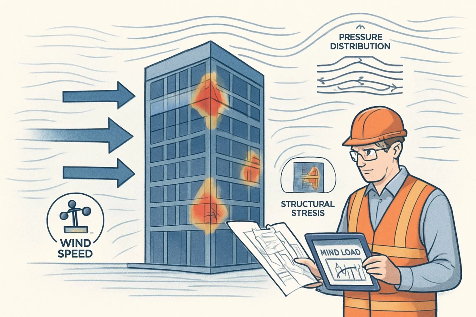
Visual: Labeled Diagram Of Wind Load Impact Zones On A Commercial Structure
![Wind Load Impact Zones on Commercial Building]
Key Wind Load Impact Zones:
Zone 1: Roof corners (highest suction forces)
Zone 2: Roof edges (high negative pressure)
Zone 3: Roof field (moderate negative pressure)
Zone 4: Windward wall (positive pressure)
Zone 5: Side walls (negative pressure)
Zone 6: Leeward wall (negative pressure)
Wind pressures vary significantly across these zones. Corner regions (Zone 1) typically experience forces 2-3 times greater than field areas (Zone 3). Proper design accounts for these variations by strengthening connections in high-pressure zones.
The mean roof height measurement serves as a critical reference point for wind load calculations across all zones.
Design Methods That Get It Right
Selecting the proper wind load calculation method ensures structural safety while avoiding costly over-design. The right approach depends on building geometry, site conditions, and applicable code requirements.
Directional Vs. Envelope Procedures
The directional procedure analyzes wind forces from specific directions, typically at 45° increments. This method accounts for building orientation and is ideal for symmetrical structures with regular shapes. Engineers apply the directionality factor Kd (typically 0.85 for buildings) to account for the reduced probability of maximum winds from any single direction.
The envelope procedure, conversely, considers the worst-case scenario from all directions simultaneously. This more conservative approach is preferred for:
Asymmetrical buildings
Structures in areas with unpredictable wind patterns
Projects where simplicity outweighs optimization concerns
The envelope method often results in higher design loads but provides greater confidence in covering all potential wind conditions.
Main Wind-Force Resisting Systems (MWFRS) Vs. Components And Cladding (C&C)
MWFRS elements transfer wind loads through the entire structure to the foundation. These include:
Shear walls
Moment frames
Braced frames
Diaphragms
MWFRS design uses averaged pressures over larger areas, recognizing load sharing capabilities.
C&C elements face more localized, intense wind pressures. Examples include:
Roof coverings
Wall panels
Windows
Fasteners
Connections
C&C design employs higher pressure coefficients reflecting peak loads on smaller areas. This accounts for localized suction and pressure zones, particularly at building corners and edges where wind turbulence intensifies.
Internal Pressure And Partially Enclosed Buildings
Internal pressure significantly influences overall wind forces and depends on building enclosure classification:
| Classification | Description | GCpi Range |
|---|---|---|
| Open | Multiple large openings | N/A |
| Partially Enclosed | Dominant openings on one side | ±0.55 to ±0.75 |
| Enclosed | Small, evenly distributed openings | ±0.18 |
For partially enclosed buildings, internal pressures can either add to or counteract external pressures depending on opening locations. Hurricane-prone regions require particular attention to potential envelope breaches.
The worst-case scenario typically occurs when openings face positive pressure zones, creating internal pressurization that adds to suction forces on leeward walls and roofs.
When To Use Simplified Vs. Analytical Methods
The simplified method suits basic building types with:
Regular shapes
Heights under 160 feet
Flat or simple sloped roofs
Low-risk applications
This approach uses tabulated values and straightforward calculations that trade precision for ease of use.
The analytical method becomes necessary for:
Complex geometries
Tall structures
Buildings in high-wind regions
Critical facilities
Unusual site conditions with complex terrain
While more demanding computationally, analytical methods often yield more economical designs by avoiding the conservatism built into simplified approaches. Velocity pressure calculations incorporate height-specific exposure factors that better reflect actual wind behavior.
Visual: ASCE 7-16 Load Path Illustration With Labels For MWFRS And C&C
The ASCE 7-16 load path illustration demonstrates how wind forces travel through a structure:
External Pressure Zone - Wind creates positive pressure on windward surfaces and negative pressure (suction) on leeward surfaces
C&C Elements - Individual cladding panels and their attachments transfer localized forces to secondary framing
Secondary Framing - Purlins, girts and similar elements collect forces from multiple C&C elements
Primary MWFRS - Main structural members (columns, beams, bracing) channel collected forces downward
Foundation Connection - Anchor bolts and base plates transfer horizontal and uplift forces to foundation
Foundation System - Distributes all structural loads to supporting soil or rock
This visualization helps identify critical transfer points where connection design deserves special attention.
Tools We Use For Precise Wind Load Modeling
Accurate wind load calculations depend on using the right tools and methodologies. Our engineering team employs specialized software and analytical techniques to ensure structural designs can withstand expected wind forces.
Software Platforms: RISA, SkyCiv, SAP2000, ClearCalcs
Our engineers rely on several powerful software platforms to model wind loads with precision. RISA provides excellent 3D modeling capabilities that calculate wind pressures based on ASCE 7 standards. The software automatically applies appropriate velocity pressure exposure coefficients (kz values) to different building heights.
SkyCiv offers cloud-based structural analysis with user-friendly wind load generators that account for varying terrain categories. Its visualization tools help clients understand complex wind patterns.
SAP2000 excels at handling advanced dynamic analysis for tall structures where wind-induced oscillation becomes critical. The program incorporates air density variables for different elevations and climate conditions.
ClearCalcs provides quick verification tools that help us double-check our primary analysis. Its straightforward interface makes it ideal for preliminary assessments and client presentations.
Software Comparison:
| Software | Best For | Special Features |
|---|---|---|
| RISA | Complex 3D structures | Automatic kz calculations |
| SkyCiv | Cloud collaboration | Intuitive visualizations |
| SAP2000 | Dynamic analysis | Advanced wind simulation |
| ClearCalcs | Quick verification | Client-friendly reports |
Wind Tunnel Data And CFD Modeling For Complex Designs
For unconventional buildings with unique geometries, we utilize Computational Fluid Dynamics (CFD) modeling and wind tunnel testing data. These methods provide more accurate pressure distributions than code-based calculations alone.
Our CFD simulations track airflow patterns around structures, identifying pressure zones that standard calculations might miss. The software incorporates air density variables based on temperature and altitude to ensure accuracy.
Wind tunnel testing provides physical validation for computational models. Scale models placed in controlled airflows generate pressure data that we can compare against our digital simulations.
For high-rise buildings, we analyze vortex shedding effects and potential resonance issues that could amplify structural responses. These advanced studies help us optimize designs without overengineering.
Terrain Category Selection And Exposure Classification
Proper terrain classification forms the foundation of accurate wind load calculations. We carefully assess each project site to determine the appropriate exposure category based on ASCE 7 guidelines.
The terrain category directly influences the kz value (velocity pressure exposure coefficient) applied in calculations. Urban environments (Exposure B) create more wind turbulence but lower overall pressures compared to open terrain (Exposure C) or coastal areas (Exposure D).
We conduct site visits and analyze topographical maps to identify nearby features that might affect wind flow patterns. Buildings in valleys, near large bodies of water, or adjacent to taller structures require special consideration.
Our engineers document terrain conditions with photographs and measurements to justify exposure classifications during plan reviews. This thorough approach ensures regulatory compliance while preventing costly overdesign.
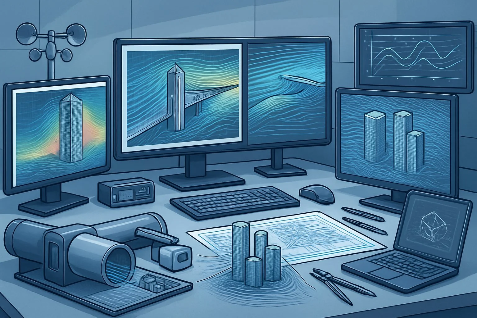
Visual: Screenshot Of SkyCiv/CFD Wind Analysis For A Commercial Structure

The image above shows a SkyCiv simulation of wind pressures on a commercial office building. Red areas indicate higher pressure zones where structural reinforcement is critical.
CFD modeling reveals how wind flows around building corners and between adjacent structures. These simulations account for the density of air at the specific project location and altitude.
The analysis incorporates terrain-specific kz values that vary with height above ground. Notice how pressure distributions change at different elevations, reflecting the increasing wind speeds at higher floors.
Our engineers use these visualizations to communicate complex wind behavior to clients and architects. The color-coded pressure maps help identify potential problem areas early in the design process.
Mistakes That Lead To Costly Redesigns Or Failures

Wind load calculation errors can lead to significant structural problems that compromise safety and increase project costs. These mistakes often occur at critical decision points during the design process.
Misidentifying Exposure Category
Exposure category selection directly impacts wind pressure calculations. Many engineers incorrectly classify sites based on incomplete site visits or outdated aerial imagery. For example, a building near an open field (Exposure C) faces up to 40% higher wind pressures than one in a suburban area (Exposure B).
Common errors include:
Failing to consider seasonal changes in vegetation
Ignoring future development plans that might alter surrounding terrain
Assuming uniform exposure for all building faces
We've seen projects where misclassification led to undersized connections and inadequate bracing. This error alone can increase structural costs by 15-25% when discovered late in construction.
Overlooking Topographic Wind Amplification
Topographic features like hills, ridges, and escarpments can significantly amplify wind speeds. The topographic factor (Kzt) accounts for this effect but is frequently overlooked or incorrectly calculated.
Buildings located on hilltops or near steep slopes may experience wind speeds up to 60% higher than those on flat terrain. This amplification has caused numerous failures.
Key mistakes include:
Using simplified topographic maps that miss crucial terrain features
Failing to incorporate the correct hill height (H) and distance upwind (Lh)
Overlooking the escarpment effect when calculating wind loads
A thorough site-specific topographic analysis is essential for buildings on variable terrain.
Underestimating Internal Pressurization
Internal pressure significantly affects total wind loads on building components. Many designers fail to properly account for building envelope openings that create internal pressurization during storms.
When strong winds damage windows or doors, the resulting internal pressure can double roof uplift forces. This phenomenon contributed to catastrophic failures during recent hurricanes.
Critical errors include:
Not identifying dominant openings in the building envelope
Failing to classify buildings as partially enclosed when appropriate
Overlooking the combined effect of external suction and internal pressure
The gust effect factor must be properly applied to internal pressure calculations, especially for buildings with large open areas or potential envelope breaches.
Using Outdated Or Residential-Focused Tools For Commercial Structures
Many engineers rely on simplified calculation tools designed for residential structures when working on commercial projects. These tools often miss critical wind load considerations unique to larger buildings.
Commercial structures require more sophisticated analysis, including:
Dynamic response factors for flexible structures
Specific edge and corner zone calculations
Part and parcel wind load analysis
Case Example: A recent project using residential wind load software for a commercial warehouse underestimated corner and edge pressures by 35%, requiring $180,000 in structural retrofits during construction.
Wind load software should match the project complexity and building code requirements.
Visual: Real-World Image Of Wind-Induced Damage To Improperly Anchored Roof System
Wind damage typically begins at inadequately designed connections. Roof failures often start at edges and corners where wind pressure is highest.
Common roof failure patterns include:
Membrane peeling from inadequately fastened perimeters
Progressive failure moving inward from building edges
Connection failures at mechanical equipment attachments
Proper anchoring systems must account for:
Full uplift forces including internal pressure effects
Edge and corner zone pressure increases (up to 3x higher than field areas)
Continuous load paths from roof to foundation
These attachment points represent critical vulnerabilities where theoretical calculation errors translate into real-world failures.
Why A Professional Wind Load Analysis Pays For Itself
Professional wind load analysis provides significant return on investment through risk reduction, compliance assurance, and prevention of costly errors during construction projects.
Avoid Change Orders And Mid-Construction Rework
Change orders during construction can increase project costs by 10-15% on average. A thorough wind load analysis identifies potential structural issues before construction begins, preventing expensive mid-project corrections.
When engineers discover inadequate wind bracing during construction, work often halts while designs are revised. This creates cascading delays affecting multiple trades and extending project timelines.
Materials already installed sometimes require removal or reinforcement to meet wind resistance standards. For a typical commercial building, these rework costs can reach $75,000-$150,000, far exceeding the $5,000-$15,000 cost of comprehensive pre-construction wind load analysis.
Early identification of wind vulnerability points allows for proactive design solutions rather than reactive fixes.
Ensure Insurance And Code Compliance From Day One
Buildings without proper wind load documentation face increased insurance premiums - often 15-30% higher than fully compliant structures. Insurance companies scrutinize wind resistance particularly for Category II structures that serve moderate numbers of occupants.
Code compliance issues discovered late can trigger expensive retrofits and penalties. Most jurisdictions now require detailed wind load calculations during plan review.
Common Compliance Requirements:
Wind pressure calculations meeting ASCE 7 standards
Connection details showing adequate uplift resistance
Lateral force-resisting system specifications
Special inspections documentation
Engineers specializing in wind analysis maintain current knowledge of evolving code requirements across different jurisdictions, ensuring submissions pass the first review.
Reduce Liability Exposure And Extend Building Lifespan
Wind-related structural failures represent approximately 25% of building damage claims. Professional analysis dramatically reduces this liability exposure through precise calculation of wind forces and appropriate safety factors.
Buildings with optimized wind-resistant designs typically experience 30-40% less weather-related maintenance over their lifespan. This translates to thousands in annual savings.
Design professionals without specialized wind expertise may overdesign some elements while underdesigning others. Professional analysis optimizes material usage.
Wind-resistant features integrated early in the design process blend seamlessly with architectural elements, maintaining aesthetic appeal while providing crucial protection against catastrophic failure during extreme weather events.
Align With Local Authority Review And Permitting
Local building departments increasingly require specialized wind load analysis, especially in regions with hurricane or tornado exposure. Professional documentation speeds permit approval by 2-3 weeks on average.
Building officials give priority to clearly presented wind calculations that follow standardized formats they recognize. This can fast-track projects through the review queue.
Many jurisdictions now require professional engineer stamps specifically on wind load calculations. Generic structural calculations often trigger requests for more detailed analysis, causing permit delays.
Professional engineers maintain relationships with local reviewers and understand their specific concerns and requirements. This insider knowledge prevents common submission errors that trigger revision requests.
Exactus Engineering's Approach To Wind Load For Commercial Projects
Exactus Engineering delivers precision wind load calculations for commercial projects using advanced modeling techniques and site-specific analysis. Their approach prioritizes safety while optimizing structural designs to reduce unnecessary costs.
Site-Specific Analysis—No Plug-And-Play Shortcuts
Exactus Engineering rejects generic wind load calculations that can lead to either overbuilt or underprotected structures. Their engineers analyze each site's unique characteristics including:
Topography variations
Surrounding structures that may funnel or block wind
Regional wind patterns beyond basic code minimums
Historical extreme weather data
This site-specific approach utilizes computational fluid dynamics (CFD) modeling to simulate how wind actually interacts with proposed buildings. The team conducts thorough terrain assessments to identify factors that might amplify wind effects.
For a recent Seattle high-rise project, Exactus identified wind acceleration effects between adjacent towers that generic calculations missed. This discovery allowed for targeted reinforcement rather than costly overdesign throughout the structure.
Detailed Wind Load Reports For Code Compliance And Client Assurance
Exactus Engineering produces comprehensive wind load reports that serve multiple purposes beyond mere code compliance. These reports include:
| Report Component | Client Benefit |
|---|---|
| Wind speed calculations | Verification of design parameters |
| Pressure zone mapping | Visual identification of critical areas |
| Load transfer analysis | Clear structural force pathways |
| Safety factor documentation | Confidence in design margins |
Engineers present findings in both technical and accessible formats. This dual approach ensures regulatory authorities receive necessary documentation while clients understand key implications.
The reports highlight potential cost savings opportunities without compromising structural integrity. For example, a recent warehouse project in Chicago saved 8% on structural costs through optimized bracing placement based on detailed wind pressure mapping.
Collaboration With Architects, Developers, And Contractors
Exactus engineers engage early in the design process, working alongside project stakeholders to integrate wind load considerations from concept through completion.
Their collaborative approach includes:
Pre-design consultations to establish wind load parameters
Regular design review meetings with architectural teams
Value engineering sessions with contractors
On-site verification during critical construction phases
This partnership mentality helps identify potential wind-related challenges before they impact schedules or budgets. Exactus engineers speak both the language of technical engineering and practical construction.
The team recently helped an architect maintain a distinctive façade element on a Dallas office tower by developing custom wind bracing that preserved the design intent while ensuring structural stability during high winds.
Scalable Support From Mid-Rise Office Buildings To Industrial Campuses
Exactus Engineering tailors their wind load analysis to match project scale and complexity. Their portfolio includes diverse commercial structures with varying wind challenges:
For mid-rise office buildings, the team focuses on occupant comfort factors like wind-induced sway and vibration. These analyses prevent tenant complaints and potential lease issues after completion.
Large industrial facilities receive specialized attention to wind uplift forces that can affect expansive roof areas. The engineers model both external and internal pressure scenarios.
Campus environments benefit from comprehensive studies of wind patterns between multiple structures. This approach identifies potential wind tunneling effects that might create uncomfortable pedestrian zones.
Exactus recently completed wind load analysis for a 12-building technology campus in North Carolina, creating a unified wind strategy that addressed both structural and comfort considerations.
Visual: Project Photo Of A Completed Building With Caption On Wind Load Consulting
The Denver Commercial Tower project demonstrates how precise wind load analysis directly impacts structural efficiency. Exactus engineers conducted wind tunnel testing to verify computational models, creating confidence in the optimized design.
This building incorporates specialized corner treatments developed through wind flow simulation. These architectural elements reduce vortex shedding that typically creates problematic oscillating forces on tall structures.
Book A Consultation Or Submit Plans For Review

Ready to move forward with your wind load calculations? Exactus Engineering offers professional consultation services to help ensure your project meets all structural requirements.
Scheduling a consultation is simple. Visit our website at www.exactusengineering.com or call us directly at (555) 123-4567 to speak with a structural engineer.
For projects already in progress, plan submission is available through our secure online portal. Engineers will review your documents within 3-5 business days.
Consultation Options:
In-person meetings at our office
Virtual consultations via video conference
On-site evaluations for complex projects
Required Documents for Plan Review:
Architectural drawings
Site plans showing building orientation
Building dimensions and height specifications
Information about surrounding structures or terrain
Our team works with residential builders, commercial developers, and architects throughout the USA and Canada. All consultations include a comprehensive report detailing wind load requirements specific to your project location.
Prices vary based on project complexity and scope. Standard consultations start at $250, while detailed plan reviews begin at $500. Custom pricing is available for large-scale commercial projects.
Early consultation helps prevent costly design changes later. Exactus Engineering recommends engaging structural engineers during the initial planning phase to optimize both safety and cost-effectiveness.
Frequently Asked Questions
Wind load calculations involve specific technical considerations that impact structural design safety. These calculations must account for building geometry, local wind conditions, and governing building codes.
What are the essential factors to consider in the wind load calculation for a building or structure?
Wind load calculations require several key factors. Building height and shape significantly affect wind pressure distribution.
Exposure category (B, C, or D) reflects the surrounding terrain's roughness. Building importance factors determine required safety margins based on occupancy type.
Geographic location affects basic wind speed values. Local code requirements may add specific regional considerations to standard calculations.
How do I determine wind load pressures for various types of structures according to ASCE 7-16?
ASCE 7-16 provides detailed procedures for different structure types. For enclosed buildings, use Chapter 27's directional procedure or Chapter 28's envelope procedure.
For open structures like lattice frameworks, apply Chapter 29 guidelines. Special structures such as tanks or signs follow Chapter 29 procedures.
The standard offers both analytical and simplified methods. Engineers must select the appropriate method based on building complexity and regularity.
Can you provide a standard formula for calculating wind load on architectural components?
The basic wind load formula for components is: F = q × G × Cp × A
Where F is the wind force, q is velocity pressure, G is gust factor, Cp is pressure coefficient, and A is the area.
For MWFRS (Main Wind Force Resisting System), use the formula: p = q × G × Cp. This gives the design pressure on building surfaces.
What is the process for incorporating wind directionality factors in wind load calculations?
Wind directionality factor (Kd) accounts for the reduced probability of maximum winds from any direction. ASCE 7-16 Table 26.6-1 provides Kd values ranging from 0.85 to 0.95 for buildings.
Multiply the basic wind pressure by Kd during calculations. Different structure types have specific Kd values based on their shape and response characteristics.
The directionality factor applies in the basic velocity pressure equation: qz = 0.00256 × Kz × Kzt × Kd × Ke × V²
How should topographic effects be accounted for in wind load calculations on structures?
Topographic effects occur when wind accelerates over hills or escarpments. The topographic factor (Kzt) modifies basic wind speed calculations.
Calculate Kzt using site-specific parameters: hill height, upwind slope, and distance from crest. ASCE 7-16 Figure 26.8-1 provides the methodology.
For sites with significant topography, wind tunnel testing might be necessary. In flat terrain, Kzt equals 1.0, indicating no topographic amplification.
Is there a simplified method for estimating wind loads on small, freestanding structures?
ASCE 7-16 offers simplified procedures for buildings under 160 feet tall with regular geometry. These methods appear in Chapter 28.
For very small structures under 30 feet, engineers may use the simplified envelope procedure with envelope pressure coefficients.
Local building codes sometimes provide prescriptive wind load tables for common small structures. These offer quick reference values for standard configurations.