Non-Destructive Testing Methods for Critical Infrastructure Assessment
Engineers need to check if structures and materials are safe without breaking them apart. Non-destructive testing (NDT) lets professionals find cracks, defects, and weak spots in bridges, buildings, and equipment while keeping everything intact. This method saves time and money compared to taking things apart.

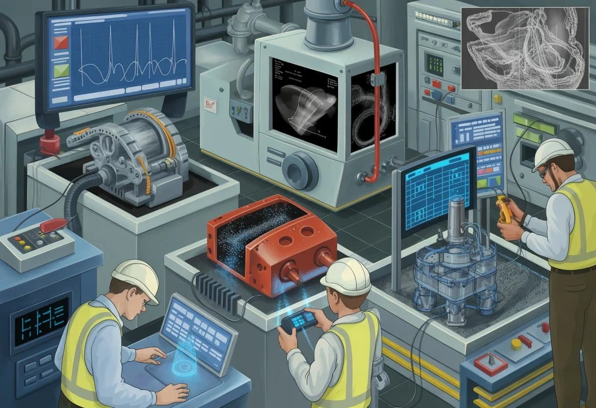
NDT uses different techniques like X-rays, sound waves, and magnetic fields to look inside materials. Each method works best for specific problems and materials. Some find surface cracks while others detect deep flaws that could cause failures.
This testing keeps people safe and prevents disasters in construction, manufacturing, and infrastructure. The field offers many career paths and requires special training to master the various methods and equipment used across industries.
Fundamentals of Non-Destructive Testing
Non-destructive testing represents a critical engineering discipline that evaluates materials and structures without causing permanent damage. This field has evolved from basic visual inspections to sophisticated technological methods that surpass traditional destructive approaches.
Definition and Purpose
Non-destructive testing (NDT) examines materials, components, and structures to detect flaws without altering their usability. Engineers also call this process non-destructive evaluation (NDE) or non-destructive examination.
NDT serves multiple essential functions in engineering:
Safety assurance through flaw detection
Quality control during manufacturing
Maintenance planning for existing structures
Cost reduction by preventing failures
The primary goal involves identifying defects like cracks, voids, or material degradation before they cause structural problems. This approach protects both human safety and financial investments.
Engineers use NDT to evaluate welds, concrete structures, aircraft components, and pipeline systems. The testing occurs during manufacturing, construction, and regular maintenance cycles.
Historical Development of NDT
NDT began with simple visual inspections in ancient construction projects. The industrial revolution created demand for more sophisticated testing methods.
Key milestones shaped modern NDT:
| Year | Development |
|---|---|
| 1895 | X-ray discovery enables internal imaging |
| 1920s | Ultrasonic testing emerges |
| 1940s | Magnetic particle |
| 1960s | Eddy current testing advances |
World War II accelerated NDT development due to aircraft safety requirements. Post-war construction booms increased demand for reliable testing methods.
Modern NDT incorporates digital imaging, automated systems, and artificial intelligence. These advances improve accuracy and reduce inspection time significantly.
Comparison with Destructive Testing
Destructive testing damages or destroys samples to measure material properties. This method provides accurate strength data but renders specimens unusable.
Non-destructive testing preserves sample integrity while providing valuable information about internal conditions. However, it may not reveal all material properties that destructive methods expose.
Key differences include:
Sample preservation: NDT maintains structural integrity
Cost efficiency: NDT allows 100% inspection without material waste
Real-time monitoring: NDT enables continuous structural health assessment
Information scope: Destructive testing provides more comprehensive material data
Engineers often combine both approaches. Destructive testing establishes baseline material properties during design phases. NDT monitors actual structures throughout their service life.
The choice depends on project requirements, safety considerations, and economic factors. Critical infrastructure typically relies heavily on NDT methods.
Key Methods and Techniques in Non-Destructive Testing
Each NDT method serves specific purposes based on material type, defect location, and inspection requirements. Visual inspection examines surface conditions, while ultrasonic testing detects internal flaws using sound waves, radiographic testing reveals subsurface defects through radiation, and magnetic particle testing identifies surface cracks in ferromagnetic materials.
Visual Inspection (VT)
Visual testing represents the most fundamental NDT method used across all industries. Inspectors examine surfaces directly with the naked eye or through magnification tools.
This technique detects surface defects like cracks, corrosion, wear, and misalignment. Direct visual inspection occurs when inspectors can view surfaces within 610 millimetres at angles no less than 30 degrees.
Remote visual inspection uses tools like borescopes, mirrors, and cameras for inaccessible areas. Common equipment includes:
Magnifying glasses (2x to 10x magnification)
Borescopes for internal surfaces
High-intensity lighting systems
Measuring devices for crack sizing
Visual inspections require proper lighting levels of at least 1000 lux. Inspectors must have certified vision standards including 20/20 near and distant vision.
The method works best on clean, accessible surfaces. Limitations include detecting only surface defects and dependency on inspector skill levels.
Ultrasonic Testing (UT)
Ultrasonic testing uses high-frequency sound waves between 0.5 and 25 MHz to detect internal defects. Sound waves travel through materials and reflect back when encountering boundaries or flaws.
Pulse-echo technique sends waves into materials and measures reflected signals. The transducer acts as both transmitter and receiver. Time-of-flight calculations determine flaw depth and location.
Through-transmission method uses separate sending and receiving transducers on opposite material sides. This technique detects flaws that reduce sound transmission.
| Ultrasonic Method | Frequency Range | Typical Applications |
|---|---|---|
| Contact testing | 1–25 MHz | Welds, forgings, castings |
| Immersion testing | 2–25 MHz | Aerospace components |
| Air-coupled testing | 50–2000 kHz | Composites, honeycomb |
Ultrasonics excel at detecting internal discontinuities in metals, composites, and ceramics. The method provides precise flaw sizing and depth measurements.
Couplants like water or gel ensure proper sound transmission between transducers and test surfaces.
Radiographic Testing (RT)
Industrial radiography uses X-rays or gamma rays to create images of internal structures. Radiation passes through materials and creates shadow images on film or digital detectors.
Film radiography captures images on photographic film placed behind test objects. Dense materials and flaws appear darker on processed films.
Digital radiography uses electronic detectors for immediate image viewing. This method reduces inspection time and eliminates chemical processing.
Radiation sources include:
X-ray machines (50-450 kV range)
Iridium-192 isotopes
Cobalt-60 sources
Linear accelerators for thick sections
RT detects internal voids, inclusions, cracks, and density variations. The technique works well on welds, castings, and assembled components.
Computed tomography creates three-dimensional images through multiple radiographic projections. This advanced technique provides detailed internal views.
Safety protocols require radiation protection measures, controlled areas, and certified operators for all radiographic operations.
Calls Magnetic Particle Testing (MT)
Magnetic particle inspection detects surface and near-surface defects in ferromagnetic materials. The method magnetises test pieces and applies magnetic particles that concentrate at flaw locations.
Wet magnetic particle methods use particles suspended in liquid carriers. Fine particles provide high sensitivity for small defects.
Dry magnetic particle techniques use powder applied directly to surfaces. This method works well for large parts and rough surfaces.
Magnetisation techniques include:
Circular magnetisation - current flows through parts creating circumferential magnetic fields
Longitudinal magnetisation - coils or yokes create fields parallel to part length
Multidirectional magnetisation - simultaneous perpendicular fields detect flaws in any orientation
Fluorescent particles under ultraviolet light provide enhanced defect visibility. White light examination uses contrasting coloured particles against painted surfaces.
Magnetic particle testing requires proper field strength verification using calibrated shims or artificial flaws. Demagnetisation removes residual magnetism after inspection.
The method effectively finds fatigue cracks, grinding burns, and heat treatment defects in steel components.
Advanced and Specialised NDT Methods
These sophisticated techniques detect specific types of defects that basic methods might miss. Each method uses unique physical principles to examine materials without causing damage.
Eddy Current Testing (ET)
Eddy current testing uses electromagnetic induction to find surface and near-surface flaws in conductive materials. A coil carrying alternating current creates a magnetic field that induces eddy currents in the test material.
How ET Works:
The probe generates electromagnetic fields
Defects disrupt the current flow patterns
Changes appear as electrical signals
This method excels at detecting cracks, corrosion, and material thickness variations. ET works best on non-ferromagnetic metals like aluminum and copper.
Key Applications:
Aircraft structural inspections
Heat exchanger tube testing
Surface crack detection in welds
The technique provides rapid results and requires minimal surface preparation. However, ET cannot penetrate deeply into thick materials. Operators need extensive training to interpret complex signal patterns accurately.
Liquid Penetrant Testing (PT)
Liquid penetrant testing reveals surface-breaking discontinuities in non-porous materials. This dye penetrant testing method works on both metallic and non-metallic surfaces.
PT Process Steps:
Clean the test surface thoroughly
Apply penetrant liquid and wait
Remove excess penetrant material
Apply developer to draw out trapped penetrant
The penetrant seeps into surface cracks through capillary action. After cleaning, a developer pulls the penetrant back out, creating visible indications of defects.
Two Main Types:
Fluorescent penetrants - Viewed under UV light
Visible dye penetrants - Seen under normal lighting
Penetrant testing finds cracks, porosity, and other surface defects effectively. The method costs little and needs no special equipment. PT cannot detect subsurface flaws or work on porous materials like concrete.
Acoustic Emission Testing (AE)
Acoustic emission testing monitors stress waves released by materials under load. When cracks grow or materials deform, they emit high-frequency sound waves that AE sensors detect.
AE System Components:
Sensitive acoustic sensors
Signal amplifiers and filters
Data recording equipment
This method provides real-time monitoring of structural integrity. AE testing works particularly well for pressure vessels, bridges, and storage tanks during proof testing.
Advantages of AE:
Detects active defect growth
Monitors large structures simultaneously
Identifies critical flaw locations
The technique reveals dynamic defects that static methods might miss. However, background noise can interfere with results. AE requires structures to be under stress during testing, which limits some applications.
Thermographic Testing
Thermographic testing uses infrared cameras to detect temperature differences across material surfaces. Heat flow changes reveal internal defects, delaminations, and structural irregularities.
Common Thermographic Approaches:
Passive thermography - Uses natural temperature differences
Active thermography - Applies external heat sources
The method works by detecting thermal patterns that indicate subsurface conditions. Areas with defects often show different temperatures than surrounding sound material.
Applications Include:
Composite material inspections
Building envelope assessments
Electrical system evaluations
Thermographic testing covers large areas quickly and produces visual results that are easy to interpret. The technique works well on layered materials and coatings. Environmental conditions and surface properties can affect measurement accuracy.
Applications of Non-Destructive Testing in Industry

Non-destructive testing serves critical roles across multiple industrial sectors, from ensuring product quality during manufacturing to maintaining structural safety in aging infrastructure. Advanced robotics and automation technologies continue to expand these capabilities.
Manufacturing and Quality Control
Manufacturing industries rely heavily on NDT methods to maintain product standards without damaging components. Ultrasonic testing detects internal flaws in welds, castings, and forgings during production.
Automotive manufacturers use magnetic particle inspection to identify surface cracks in engine blocks and transmission components. This process saves thousands of dollars by catching defects before final assembly.
Aerospace companies employ radiographic testing to examine critical aircraft components. X-ray and gamma-ray techniques reveal hidden voids in composite materials and metal structures.
Key NDT applications in manufacturing:
Weld quality verification
Material thickness measurement
Porosity detection in castings
Bond integrity in layered materials
Surface finish evaluation
The electronics industry uses eddy current testing to inspect printed circuit boards and semiconductor components. This method identifies electrical discontinuities without physical contact.
Quality control teams integrate NDT equipment into production lines for real-time monitoring. Automated systems flag defective parts immediately, reducing waste and rework costs.
Structural Integrity and Safety
Infrastructure maintenance depends on regular NDT assessments to prevent catastrophic failures. Penetrant testing reveals surface-breaking cracks in bridges, pipelines, and pressure vessels.
Power plants use acoustic emission testing to monitor reactor vessels and steam generators during operation. This technique detects crack growth in real-time without shutting down equipment.
Common structural applications include:
Bridge deck delamination mapping
Concrete rebar corrosion assessment
Pipeline wall thickness monitoring
Fatigue crack detection in steel structures
Corrosion evaluation in storage tanks
Oil and gas companies conduct regular ultrasonic thickness testing on pipelines to monitor corrosion rates. This data helps predict remaining service life and schedule maintenance.
Building inspectors use ground-penetrating radar to locate reinforcement bars and voids in concrete structures. This information guides repair decisions and structural modifications.
Railway operators employ magnetic flux leakage testing to inspect rail tracks for internal defects. Specialized equipment travels at high speeds while scanning for potential failure points.
Emerging Technologies and Robotics
Robotic NDT systems access hazardous or hard-to-reach areas where human inspectors cannot safely operate. Drone-mounted cameras with thermal imaging capabilities inspect tall structures and offshore platforms.
Crawling robots equipped with ultrasonic sensors navigate inside pipelines and pressure vessels. These systems collect data continuously while mapping internal conditions.
Machine learning algorithms analyse NDT data patterns to predict component failures before they occur. This predictive maintenance approach reduces downtime and maintenance costs.
Advanced robotic applications:
Underwater hull inspections on ships
Nuclear reactor vessel examinations
Wind turbine blade assessments
Storage tank floor surveys
Aircraft fuselage scanning
Artificial intelligence enhances defect recognition accuracy in radiographic images. Computer vision systems identify anomalies faster than traditional manual interpretation methods.
Portable NDT devices now connect wirelessly to cloud-based databases for instant results comparison. Field technicians access historical data and expert analysis remotely during inspections.
Frequently Asked Questions
Non-destructive testing methods vary in their applications and capabilities. Each technique detects specific types of flaws and works best with certain materials or structural conditions.
What are the most common methods used in non-destructive examination?
Visual testing remains the most widely used method across all industries. Inspectors examine surfaces for cracks, corrosion, and other visible defects using the naked eye or magnification tools.
Ultrasonic testing uses high-frequency sound waves to detect internal flaws. This method works well for thickness measurements and finding cracks in metals, welds, and composites.
Magnetic particle testing applies to ferromagnetic materials like steel. It reveals surface and near-surface defects by using magnetic fields and iron particles.
Radiographic testing employs X-rays or gamma rays to create images of internal structures. This technique shows internal defects, density changes, and material variations.
Liquid penetrant testing finds surface-breaking defects in non-porous materials. Coloured or fluorescent liquids seep into cracks and make them visible under proper lighting.
How do you determine the appropriate non-destructive testing technique for a particular material or structure?
Material type forms the primary consideration when selecting testing methods. Ferromagnetic materials allow magnetic particle testing, while non-magnetic materials require different approaches.
The location and type of expected defects influence method selection. Surface defects suit visual or penetrant testing, while internal flaws need ultrasonic or radiographic methods.
Access to the component affects technique choice. Some methods require access to both sides of the material, while others work from one side only.
Safety considerations and environmental factors play important roles. Radiographic testing requires radiation safety protocols, while magnetic particle testing needs proper ventilation for wet methods.
Cost and time constraints often determine the final selection. Some methods provide faster results but may cost more in equipment or training requirements.
What is the difference between ultrasonic testing and radiographic testing?
Ultrasonic testing uses sound waves that bounce back from defects or material boundaries. The operator places a probe directly on the material surface and reads results immediately on a screen.
Radiographic testing uses penetrating radiation to create images on film or digital detectors. This method requires the radiation source on one side and the detector on the opposite side of the component.
Ultrasonic testing provides instant results and poses no radiation hazard to operators. However, it requires direct contact with the material and skilled technicians to interpret results.
Radiographic testing produces permanent images that document defect locations and sizes. It penetrates thick materials better but involves radiation safety concerns and longer processing times.
Ultrasonic testing excels at measuring thickness and detecting laminar defects. Radiographic testing better shows the actual shape and orientation of internal flaws.
Can non-destructive testing ensure the complete safety of structures and materials?
Non-destructive testing significantly improves safety but cannot guarantee complete protection against all failures. These methods detect many defects but may miss some flaws due to technique limitations.
Each testing method has specific detection capabilities and blind spots. Small defects below the detection threshold may remain undetected during inspection.
Human factors influence testing reliability. Operator skill, fatigue, and environmental conditions affect inspection quality and defect detection rates.
Equipment limitations and calibration issues can reduce testing effectiveness. Proper maintenance and regular calibration help maintain detection capabilities.
Non-destructive testing works best as part of a comprehensive safety program. Regular inspections, proper maintenance, and following engineering standards provide multiple layers of protection.
What types of defects can magnetic particle testing detect?
Surface cracks appear clearly with magnetic particle testing when they interrupt the magnetic field. These include fatigue cracks, grinding cracks, and heat treatment cracks in steel components.
Subsurface defects within approximately 6 millimetres of the surface create detectable indications. The exact depth depends on defect size, orientation, and material properties.
Seams and laps from manufacturing processes show up as linear indications. These defects often occur parallel to the material surface or rolling direction.
Inclusions and voids near the surface disrupt magnetic fields and attract magnetic particles. Non-metallic inclusions and porosity become visible during proper inspection procedures.
Cold shuts and forging defects create clear indications when properly oriented to the applied magnetic field. Part geometry and magnetisation direction affect defect visibility.
How frequently should periodic non-destructive evaluations be conducted on critical infrastructure?
Critical infrastructure requires inspection schedules based on consequence of failure and operating conditions. High-risk components need more frequent evaluation than lower-risk elements.
Bridges typically undergo detailed inspections every two years with more frequent routine checks. Special inspections occur after extreme weather events or when problems arise.
Pressure vessels follow inspection intervals set by codes and regulations. These range from annual external inspections to internal examinations every few years.
Aircraft structures have mandatory inspection intervals based on flight hours or cycles. Critical components may require inspection after every few hundred flights.
Industrial equipment inspection frequency depends on operating severity and manufacturer recommendations. Harsh environments or high stress applications need more frequent evaluation.
Pipeline integrity programs specify inspection intervals based on risk assessments and regulatory requirements. High-consequence areas receive priority scheduling for evaluation activities.